I've always found electronics interesting. Yet when I found out that average components like resistors, capacitors, and diodes could be used in configuration to make an effect, I asked myself...how does it work? This is how I got the idea for this post. In this post, I will be explaining how the Way Huge Red Llama works. I built this pedal about a week ago and I can say it is a pretty sweet sounding overdrive/fuzz hybrid.
The Red Llama is actually a clone itself with some component changes. The original designer of the circuit is Craig Anderson. In an interview with Jeorge Tripps, creator of the way huge line, he said that he had bought this book called "Electronic Projects for Musicians" written by Craig Anderson. He also said that the first pedal he built was the Tube Sound Fuzz that was that book. Once I heard that this book existed, I quickly got it. In this book, Craig Anderson talks about the circuit. He explains how it works, why it works, and the reason it sounds so good.

These pictures just give a kind of overview of the circuit and talks a little bit about the sound

In the "background" section of the page, he talks about the use of field effect transistors or FET for distortion that has tube qualities. But in this project, he does't use FET transistors. The main amplifying section of this circuit is a CMOS hex inverter.


 This is my favourite setting. It gives a real nice crunch to your amp


The volume knob on this thing is incredible. It is really ear shattering it get's so loud.


 To see the top of the wave, I had to switch the volts per division switch. So the scale of this smaller than the scale of the other pictures

I'm really glad I was able to do this. I learned a lot in the process. There is still a lot that is still confusion about audio electronics. But now I can say that I know how a CMOS hex inverter pushes the signal into overdrive to achieve a tube sound fuzz!
The Red Llama is actually a clone itself with some component changes. The original designer of the circuit is Craig Anderson. In an interview with Jeorge Tripps, creator of the way huge line, he said that he had bought this book called "Electronic Projects for Musicians" written by Craig Anderson. He also said that the first pedal he built was the Tube Sound Fuzz that was that book. Once I heard that this book existed, I quickly got it. In this book, Craig Anderson talks about the circuit. He explains how it works, why it works, and the reason it sounds so good.

These pictures just give a kind of overview of the circuit and talks a little bit about the sound


Most overdrive circuits use an amplifier. Either an op-amp (tube screamer) or a transistor (Lovepedal COT 50). The same way if you push a tube amp, it will overdrive, if you push and op-amp or FET it will do the same.
The CMOS 4049 IC chip has multiple amplifiers in it. This pedal only uses two.

The best way to analyze a circuit is to look at the schematic. Luckaly, Craig Anderson gave it to us in his book
Basically there is two amplifying stages to this circuit. The first one amplifies the input signal and the second one will get overloaded and gets distorted. The picture of text also explains what all the other components do.
This last piece of text he speaks highly of his creation. It really is a very nice effect, it is a tube sounding fuzz.
All the pieces of text that I have pictures of is from this section "how it works"
Another thing I want to do with this post is show what the wave form looks like on an oscilloscope. I was very fortunate that my high school was able to let me borrow an oscilloscope from their physics lab. I've had a lot of fun playing around with this thing.
I like to use my function generator as the input of the effect so I can see a nice and clean wave form. I keep it at 440Hz just cause thats an A on a guitar

From the function generator, or wave form generator, there are two cable that come out of it. The ground, black, and the signal, red. Since the pedal uses 1/4 inch jacks, I need to hook up the two probes to the jacks like so

The oscilloscope also has two probes but the configuration is different. There is one hook type thing, the signal, and the ground, alligator clip

After everything is hooked up properly, I just need to attach cables to and from the pedal
The bypassed signal is a nice and simple sign wave

The cool thing about this pedal it how dynamic it is.
On the wave form generator, there is a knob that controls the amplitude or the strength of the signal. This knob would be equivalent to your playing dynamics.
This photo show the wave form with a very small amplitude, almost like you are barely strumming the guitar

And with the amplitude turned up some more the wave takes more of a square wave shape but not quite there yet

With the amplitude in the middle, the wave is fairly square. All fuzz boxes have a square wave form

With the level of the wave form set kinda high, the corners of the wave get sharper


Depending on what pickups you use and the dynamic of your playing style, the signal will get more distorted. The pictures above had the same gain setting but just with a different amplitude.
The gain on this pedal is not too monstrous. But it does have a great tone to it. These next pictures will show the gain knob in its full spectrum with the amplitude on the function generator set the same
Really pay attention to the corners of the wave.


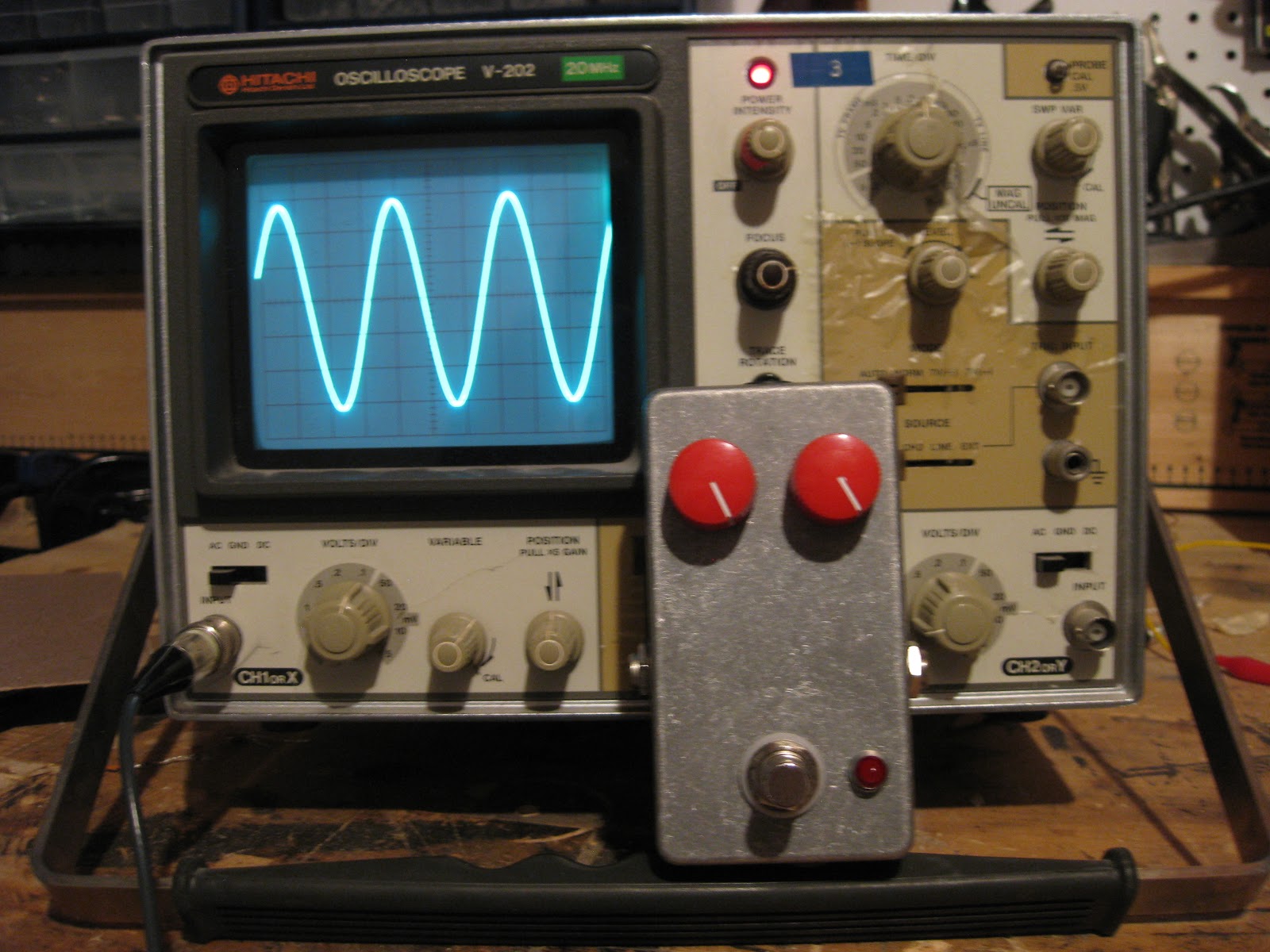
The volume knob on this thing is incredible. It is really ear shattering it get's so loud.


This next photo is of the volume knob all the way up. The wave actually goes off the screen. You might be able to see the fait green lines near the top


I'm really glad I was able to do this. I learned a lot in the process. There is still a lot that is still confusion about audio electronics. But now I can say that I know how a CMOS hex inverter pushes the signal into overdrive to achieve a tube sound fuzz!