I was listening to some early Queen and I thought to myself that the driven tone Brian may uses on some of his tunes are just pure distortion. So I decided to get my first build out, the MXR Distortion plus with Wampler mods. I have to say, when I was playing White Man, on A Day At The Races, with this pedal, I really enjoyed the sound I was getting. This kind of sound was just pure distortion tone. I'm just so glad my first build still works like a charm. A lot of people build the Distortion plus as their first build. It's an excellent pedal. I absolutely recommend as this as a first build!
Showing posts with label MXR Distortion Plus. Show all posts
Showing posts with label MXR Distortion Plus. Show all posts
Thursday, 4 July 2013

Sunday, 3 March 2013
MXR Distortion Plus build report
So at this point I'm just going to talk about the challenges I had and other this I leared along the way with this project. About half way through this project I had realized that this was a hell of a first project. I didn't know what I was thinking at the time. But I'm glad I did pick this layout because I learned a lot. So this was my first really project and it turned out great. IT WORKS!!!!! and it sound GREAT. The night I finished it up and tested it I was so happy and high on life.
Anyway, each step along this build, my knowledge of building pedal grew greater. Most of all, my soldering skills got a lot better in the way that I understand what work and what doesn't. When soldering, I learned how to apply the soldering iron in the right way to achieve greater results.
The biggest challenge that came with this project was definetly the amount of wire connecting components. How I overcame this is from planning the placements of the wire and using needle nose plier to bend them in the right way.
I'm really pleased with the outcome. Here are some beauty shots of the pedal
 The one on the left is my previous build, a fuzz

It fits perfectly with my other pedals


If I can give one piece of advise for beginner pedal builders, I would say double check everything before you solder. I know I said this a lot during this build, but I really do mean it. If you are 100% sure of what you are doing, it most likely will work. Also another thing to point out, this is not a race, take your time and pursue through the tough parts.
I would suggest a little simpler layout and a big enclosure to take out all the troubles of compacting wires.
If you do decide to build this layout, I wish you the best of luck.
Happy soldering
Anyway, each step along this build, my knowledge of building pedal grew greater. Most of all, my soldering skills got a lot better in the way that I understand what work and what doesn't. When soldering, I learned how to apply the soldering iron in the right way to achieve greater results.
The biggest challenge that came with this project was definetly the amount of wire connecting components. How I overcame this is from planning the placements of the wire and using needle nose plier to bend them in the right way.
I'm really pleased with the outcome. Here are some beauty shots of the pedal


It sounds as good as it looks

I would suggest a little simpler layout and a big enclosure to take out all the troubles of compacting wires.
If you do decide to build this layout, I wish you the best of luck.
Happy soldering
The final step!!!
This is probably the most challenging part of this whole project, well at least for me. The final step is to connect the wires that are attached to the board to the offboard components like pots and switches. I might have exaggerated on this being the hardest part, but it did take a while. For the start of this step I just jumped right into it.

 I used my helping hand to hold the board while I solder the first wires
 I'm not to happy about this soldering job
 I would suggest having the wires cut the right length so you can have the neatly bent

 Another soldering job done wrong. I had soldered the wrong wire by mistake, I was in the moment. Anyway, I had to re heat the lug multiple times and this looks messy now. To avoid this, make sure you double check the correct wire placement so you only need to solder once.
So thats the last wire soldered to the stomp switch
 This is the last of the connections, all done. Sorry I didn't take pics along the way, as I said before I got caught up in the moment
 I know, it looks a little messy, but this layout demanded a lot of wires, good thing I got the big enclosure


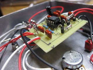
 This was a hell of a first project. I had fun throughout the whole thing
If you have any questions or comments, please them them in the comment section below


So thats the last wire soldered to the stomp switch


If you have any questions or comments, please them them in the comment section below
Saturday, 2 March 2013
Offboard soldering
This part is a very useful step that makes life, or at least this project, a lot easier. Basically it's soldering everything you can before soldering the wires connected to the board. So for example, soldering the wires of the jacks to the 3PDT switch.


 For the offboard wiring, i'll be following this diagram, apparently it doesn't allow noise to pass through the circuit. Anyway, it sound like it's worth doing (https://blogger.googleusercontent.com/img/b/R29vZ2xl/AVvXsEhyoM4rluCqZjwTSYZd8YygxHfNAeyZgBbSBl9a2uiaLXDhqpFIlTNmSLoQ9-Bahy8Oj_-HryrlSkTlQ3xJpFRZJe1I2KVOfKGfF_4xflGDbHG3Lh8gXB7evYUbP2KJ-dwsRJLgcHImOg/s1600/!Offboard+wiring.png)
Now this diagram doesn't include a batterie, but with a small modification that can be easily fixed. Instead of having two mono jacks, you need a stereo input jack. For that diagram I used this to help me out (http://www.guitarpcb.com/photos/Easy%20Pedal%20Wiring%20Diagram.jpg)
Other than that I just followed the the diagram and did everything I could before adding the board.
 The point of doing the offboard wiring first is so you can bend the wires into the best position for a nice and neat gutshot.

 Twisting the batterie snap can save some space
 Using component leads are good for making links
 Make sure the wires don't touch any other lugs or get in the way of the cable


 The schematic requires that lugs 2 and 3 of the drive pot are connected. Instead of using a component lead, I used pliers and bent them together then soldered them together. If you do do this, make sure you are still able to get the wire through the lug, like in the picture.
 Well at this point it is for the most part looking pretty clean. It's going to be ready for the board
 Needle nose pliers were are really big help throughout this step. They allowed me to bend wires with precision
If you have any questions or comments, please leave them in the comment section below


Now this diagram doesn't include a batterie, but with a small modification that can be easily fixed. Instead of having two mono jacks, you need a stereo input jack. For that diagram I used this to help me out (http://www.guitarpcb.com/photos/Easy%20Pedal%20Wiring%20Diagram.jpg)
Other than that I just followed the the diagram and did everything I could before adding the board.


If you have any questions or comments, please leave them in the comment section below
Drilling the enclosure
So I got all the components soldered onto the board. The next step for this project is to drill the enclosure.
 What I did is put masking tape and measured all the points I want to drill. Proper drilling technique is stating with a small drill bit and work your way up to the right size. You can judge the right size by placing the nut over the drill bit.
 The holes on the top row may look a little offset from the second row, but it works out with the knobs and switches

After I finished drilling, I checked if the components fit.


 I really went all out with LED, true bypass, DC jack, batterie snap and I through an LED bezel just for nice looks
When planing the measurements, keep in mind that nothing should be touching, especially the jacks and the pots.
 Well thats about all anyone would ever need to know about drilling. Some DIY pedal builders like to paint their enclosures. If you want to have a coloured enclosure, I would suggest you paint it first and drill after.

If you have any questions or comments, please leave them in the comment section below


After I finished drilling, I checked if the components fit.


When planing the measurements, keep in mind that nothing should be touching, especially the jacks and the pots.


If you have any questions or comments, please leave them in the comment section below
Wednesday, 27 February 2013
Soldering
Last post was a guide for preparing the board for components. Now we can get started on soldering in all the components. This step in the project is pretty strait forward. But there is a lot you can do to make mistakes, as i found out.
 So this is where we left off, some cuts and jumpers.
The first group of components to solder in are resistors. The reason for this is because they are the thinest of all the rest / lower profile. Soldering these first makes it easier to solder the the other components.
 It's a smart idea to keep the components in the bags they come in. The bags are labeled with the values of that component so you don't get the values mixed up.
 So with no further adieu, let's get soldering!
 One thing that I found helpful during this step is to cross of the component on the layout. This helped me know what I soldered and what needs to be soldered.
Another tip is to prebend the components so you don't put stress on the leads.
 So with all the resistors soldered in, it looks a little like this. There is also a socket for the IC. IC sockets are so easy because you can't overheat the sockets.
 This is what mine looked like, not to bad!
The next set of components to solder in are diodes, same ish shape to resistors. I had bought a line of individual sockets and was planing on using those on the diodes. This pedal uses 4 germanium diodes. These tend to be heat sensitive. But I took a shot with soldering and socketing and realized that soldering was easier. I soldered the germanium first.
 The next diodes I soldered are silicon diodes, less heat sensitive.

 I used a cool looking technique that put the diodes vertically in the board. The reason for this is that the diodes would not fit horizontally. This is a great technique, I strongly suggest it.
The next component are capacitors.
 Pre-bending caps are useful as well, it makes a good fit. The bend technique is like the photo below.
 At this point in soldering, the solder side of my board got pretty dense. To make sure there were no solder bridges I ran an exacto knife between the strips.
 The last components are the polarized caps because they are the biggest (most of the time)
And now this is a populated board with all the components in it.


 One thing that I found out during the soldering process is that with each component that I soldered in, my technique developed further and further.
Last step is to put the IC into it's socket. Make sure to put in is the right way. But is you don't just get some pliers and take it out of it's socket, the beauty of sockets. The IC also comes with a styrofoam to protect the leads, nice touch Mammoth Electronics.


If you have any questions or comments, please leave them down in the comment section below

The first group of components to solder in are resistors. The reason for this is because they are the thinest of all the rest / lower profile. Soldering these first makes it easier to solder the the other components.


Another tip is to prebend the components so you don't put stress on the leads.


The next set of components to solder in are diodes, same ish shape to resistors. I had bought a line of individual sockets and was planing on using those on the diodes. This pedal uses 4 germanium diodes. These tend to be heat sensitive. But I took a shot with soldering and socketing and realized that soldering was easier. I soldered the germanium first.


The next component are capacitors.


And now this is a populated board with all the components in it.


Last step is to put the IC into it's socket. Make sure to put in is the right way. But is you don't just get some pliers and take it out of it's socket, the beauty of sockets. The IC also comes with a styrofoam to protect the leads, nice touch Mammoth Electronics.


If you have any questions or comments, please leave them down in the comment section below
Subscribe to:
Posts (Atom)