Thursday, 11 April 2013

Putting the guts into the Llama

The last step to this project is putting the board into the enclosure. For this build I bought a 1590b enclosure which is the second smallest you can get, it's the size of a phase 90 box. Anyway, it was a little tricky to place all the wires in the right spots, but I picked up a few simple methods. I will be using this wiring method (http://tagboardeffects.blogspot.ca/2012/02/offboard-wiring.html)

Luckily I was able to just bend the LED lead onto the switch
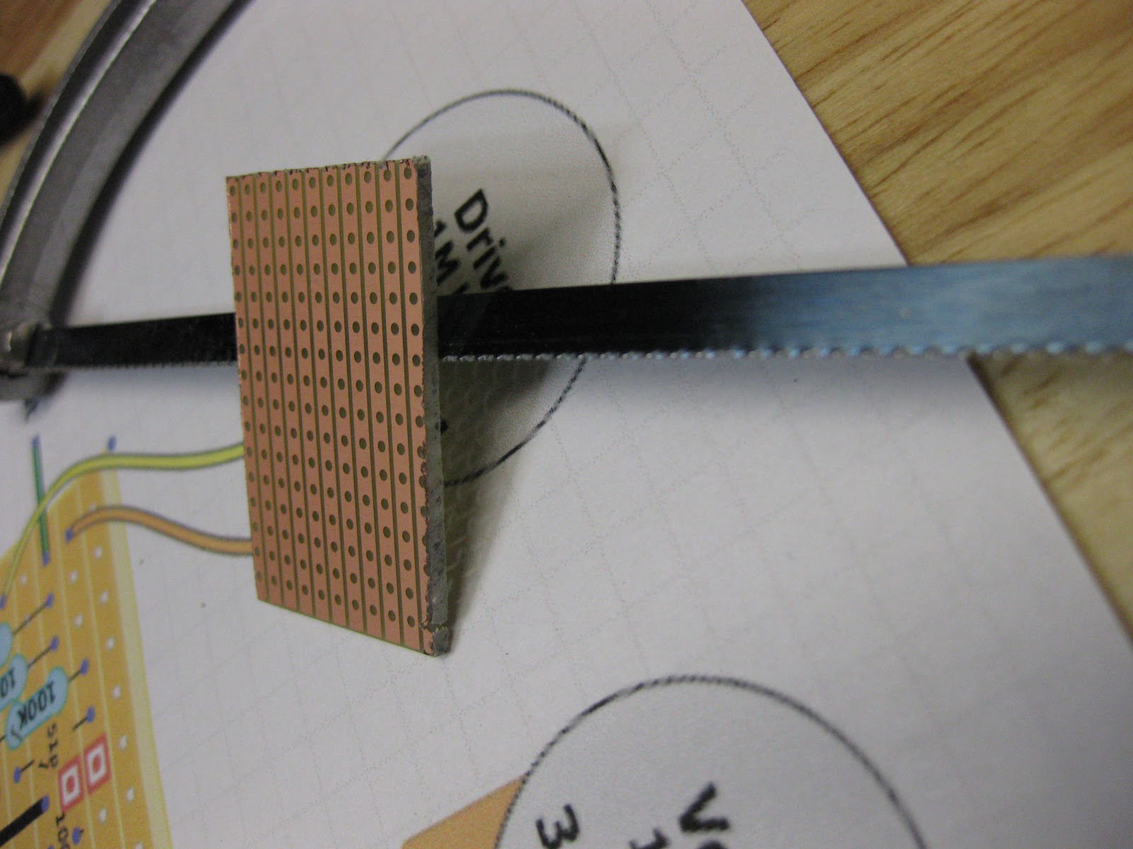
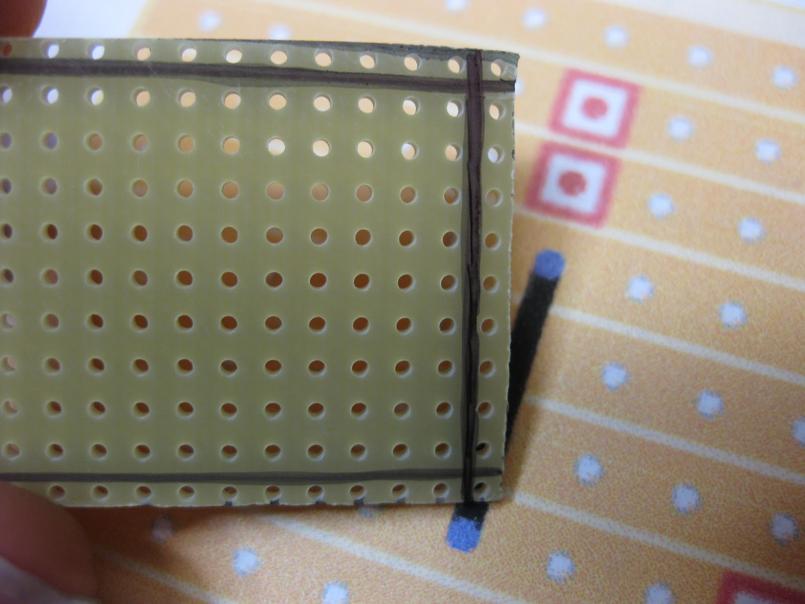
 Last time I soldered a resistor to the cathode and let it free float. but this time I wanted something a little more sturdy so I soldered it to a strip board
 That LED board work out really well
 So there are the grounds that are all connected
 I did do the twisty wire thing cause it looks cool
 I left the battery adapter unsoldered cause some wires that need to be connected to the ground and 9v
 It's a funny story, I showed my other pedal to my grandfather, who was an electrician, and when I showed him my best work and he was slightly unimpressed with the sloppy wires. So this time I wanted to prove to him that I can do better. This time around I got out the needle nose pliers and bent everything in right angle. I really did the best I can on this one.
 The battery adapter all soldered up
 This part is the most sloppy of all of them
 Soldering underneath the board to the pot lugs was the most difficult part. Take your time on this part
 I am still shocked at the amount of space that is in the enclosure
 The knobs make pedal...they really do
I'll be coming up with the build report very soon when I've had some time to play with it

Wednesday, 10 April 2013

Drilling the Llama

A little bit of a crude title but this post is about drilling the enclosure of the Red Llama. So there is nothing that special about this part. I just jump into it.

I like to mark the points to drill with masking tape. I do use calculations to find the exact centre of length for nice professional look.
These are the marks for the 3PDT stomp switch and LED. This time I drill the LED to the right side so it's easier to bend the LED leads to the stomp switch
 I like to start with a small drill bit and work my way up to a larger one
 This technique get's nice and neat cuts
 When I put the stomp switch in, I realized that it's too deep in the enclosure and it will actually touch the back plate
 Simple solution: take off the nut at the bottom, like in this picture below
 And now it has the right profile
 As I said, I can simply just bend the LED lead to reach the switch
 Good spacing
 Then the input and output jacks
 With this part, you really want to make sure that the jack is not touching the enclosure in any way (except for the part that needs to be connected)
 I double check if anything was touching the enclosure with my handy continuity tester
 I can't even tell you how useful this little thing is... i've used it a lot on this project
 For the glorious Red Llama, I got some fancy looking red knobs and red LED
 Then the pots and dc power jack need to be drilled next. I like to make a cross so I can get pretty precise with the drill bit
 When ordering the smaller enclosure, I was woried that I wouldn't have enough room...
 ...but is look like there is a lot of room considering the board only takes about half of the space
At the end of the day, I think this thing looks pretty good
I can't handle those red knobs

Monday, 8 April 2013

Soldering the Llama

So I finally had a nice time ordering parts. I didn't have any extra fees and they just left the package on my door step so I didn't have to drive all the way to UPS shop in the middle of no where. Now that i'm in a good mood I can get started on the soldering process. So this time around I got a nice soldering iron that works beautifully. This step is pretty strait forwards, I like to do a couple practice soldering on an other piece of strip board so I can get warmed up for the real thing.

First up are resistors because they are the flattest/low profile and they don't get in the way of bigger components 

 This build has a 16 pin IC chip. I do use sockets for the convenience of just being able to plop in an IC
It was a little tricky soldering in all 16 just because they are in between other solder joints but I got the job done
Next are the capacitors. I bought a couple weird looking caps like the really small ones down here and a tanatalum polarized cap. I bought them cause I thought it would be kinda cool to upgrade the quality a little 
 These caps were a pain it fit in the holes. I had to do some crazy bends on the leads to make them fit
I had to bend the tall electrolytic to the side so it keeps a low profile


 And with everything in their place, the board is complete

 My soldering did get better with practice and they're looking pretty good to me

 Of all the times I soldered, I picked up new techniques and trick to get the job done right. I can't tell you how to solder, but I can tell you that you will make up your own tricks as you solder. I just really hope I didn't mess anything up. If you want a more in depth look at this step, check out my other post about soldering

If you have any comment or questions, leave a comment down below

Sunday, 7 April 2013

Red Llama beginning

When I started this blog in late February I really didn't know what to expect. But about a month later I got 1000 views!!!! I really was amazed at the amount of people around the world looking at this blog. So I guess I just wanted to say thank you and I hope you like my future project and tutorials coming up. If you have any suggestions for me or questions, please leave a comment, I really like helping people.

I ordered parts for my next 3 projects to keep me occupied and I thought I would start off with the mighty Way Huge Red Llama!!! I picked this one first because it is the easiest (the least components on the board) out of the three. The parts haven't come in yet, they should come in this week, but I can still get started. So the first step is preparing the strip board for components. All I need to do is cut the board to size, drill the breaking points and solder the links. And now that I have my continuity tester, I can make sure everything is perfect so when the parts come in I can jump in head first and just get to soldering. 

Here is the layout I will be using, I got this layout from  http://tagboardeffects.blogspot.ca  great site. It doesn't have too many components but it's supposed to be a legendary overdrive 
 This layout is 15 long and 9 down
 I mark the size with a fine point sharpie. I went one row extra on each side for safety and other such thing
Then I just cut away with a small hand saw
The saw leaves the edges very rough
 I fix the edges by filling it down
 I left one row on each side so I marked out the 15x11 layout with sharpie
 Then I circle around the holes that need to be cut
 Then I drilled the holes so no copper was touching. If you want a more in depth explanation of this step, I explained it in this post from the distortion plus build
 Before I soldered in the links I used my continuity tester to make sure the line was completely broken
 The tricking link of this build is the 2 link under the IC. All you need to do is find some thin component leads and put both of then in the solder

 Done with that
 I can say this for sure, practice does make you better. My soldering skills have gotten way better than last time

 As the last step, I use the continuity tester I built to check if all the links have a solid connection
I would strongly suggest using some kind of tester to check this step because if you mess something up at this point, nothing else will work later on. I triple check everything with the tester to make sure when I get the parts I can just jump right in!!!

If you have any questions, comment or concerns, please leave a comment in the comment section