Sunday, 14 July 2013

Just got parts!

Living in Canada is fantastic, but it makes shipping parts really frustrating. Luckily I found a great dealer: Mammoth Electronics. The parts I ordered are for a Red Llama, that I'm building for a friend, and a Zvex Box of Rock. I've already built the Red Llama before and it sound great. As for the Box of Rock, I have heard countless good things about this pedal. It's also not that big of a build so I thought I would give it a shot! 

Since I got the parts mailed it to me, I can now start building! I promise pictures will be coming soon of my newest build. Be sure to keep checking this site because it's summer and I have a load of free time to publish my pedal adventures.

Friday, 5 July 2013

Phase 90 mods

In the summer on 2012 I was looking into a phase pedal. The obvious choice was the Phase 90 by MXR. Now they have a huge selection of phaser pedals. Sadly the one I wanted, script reissue with LED and DC power jack, was pretty expensive. The regular phase 90 was a lot less expensive compared to the script ones. I don't know how but I stumbled across this thing call the script mod. So I've heard of pedal mods before. But I never knew that it was that simple. The Script Mod was basically removing the R28 resistor from the circuit. All I had to do was cut off one of the legs of that resistor. I really like the idea of being able to have a more vintage sounding phaser, but what if I wanted to switch back to the original design if I didn't like it or if the song demanded it. This is where I got the idea of putting in a switch. I'm really glad I put in this switch. To this day I still switch between the stock and script switch to change up the sound. I did this mod last summer and since then I decided to do another mod to the Phase 90, but I'll get into that a little later. Currently my Phase 90 has 2 switches on it. One is the script mod and the other is a tremolo mod. Here are some pictures of my modded phase 90. I'll also give some tips I learned along the way with modding. 

So here it is in its beauty
The V represents vintage and that drawing is just to say what I have done with the circuit. I can switch between having the R28 resistor in or out.
Taking out the PCB isn't that difficult but putting it back in is
Here is the solder side of the PCB. Don't mind the two wires, thats for the tremolo mod
You have to take off all of the nuts before you can take out the board...
....even the jacks
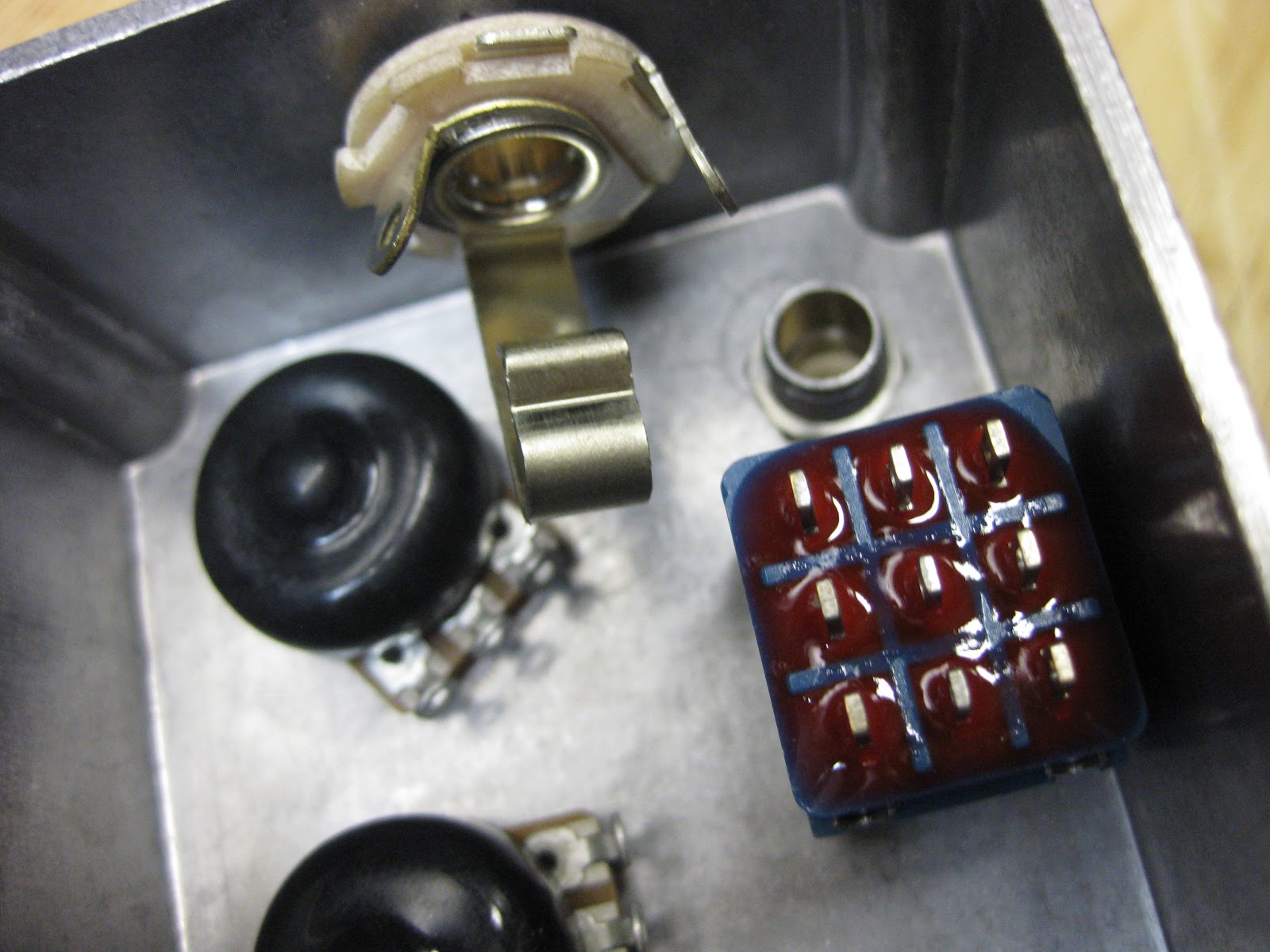
So here I have two tightly fit switches between components
This I believe is a bias knob. DO NOT TURN IT. This will change the sweep and make it sound uneven
Here is the switch for the script mod. I put electrical tape around it to make sure it doesn't short circuit.
There is the placement of the R28. Just above the output jack.
As you can see I desoldered one leg of the resistor and lifted it up.
What you want to do is have a SPST switch. I had to just snap off one leg so when it's in that position the resistor is removed. Have one wire that goes from one lug to the empty whole. Have the next wire that is soldered to the second lug be soldered to the other end of the resistor. This diagram explains it pretty well...I think.

The placement of the switch is important. You want a space that has a low profile so the switch can fit without putting stress on the board.

Next you would want to drill a whole accordingly. 


This is the next mod I decided to do, it's called the Tremolo mod. I found this in the Wampler book of pedal modifications. It's a great book, thats where I found the mod for my Marshall Guv'nor. This mod does as it's supposed to do, tremolo. But in my experience, it has kinda like a univibe characteristic to it. It does phase but it also swells the volume like a tremolo. The one thing that makes this mod not perfect is that at the peak of volume it almost distorts a little. But I can't really tell in the moment.
The mod was to put a 0.1uf cap to touch these two points in the circuit.
For the switch, what I did was have the .1uf cap flush against it for minimal space occupied
As for the placement of the two wires, one wire is attached to one lug of the switch, the other wire is soldered to one leg of the cap, and the other leg of that cap is soldered to the other lug on the switch. I hope thats not confusing. So I have the switch itself on top and the solder on the back. 
 So I can very easily take the two wires and bend the around the corner place where there is room.
Then the switch rests in-between some transistors

A vey snug fit!
So this is my phase 90. I never thought that I could do two mods but look at it now. It's a very versatile pedal for only one knob!
If you have any questions or comments about these mods, please leave them in the comment section below. 

Thursday, 4 July 2013

Distortion plus just sounds great!

I was listening to some early Queen and I thought to myself that the driven tone Brian may uses on some of his tunes are just pure distortion. So I decided to get my first build out, the MXR Distortion plus with Wampler mods. I have to say, when I was playing White Man, on A Day At The Races, with this pedal, I really enjoyed the sound I was getting. This kind of sound was just pure distortion tone. I'm just so glad my first build still works like a charm. A lot of people build the Distortion plus as their first build. It's an excellent pedal. I absolutely recommend as this as a first build!   

Saturday, 22 June 2013

EP Booster soldering

First post of SUMMER VACATION!!!!!
I've been waiting for these glorious 2 months for a long time now. And now they are finally here! Let's just jump right into it.

I've already made a lot of posts about soldering the components on the vero board. If you want a full in depth description check out some of my earlier post of my first pedal.

So here it is, the EP Booster! The EP Booster is based on the preamp circuit of the old EchoPlex tape machine. A lot of Legends: Jimmy Page, Eddie Van Hallen, Eric Johnson; use the echoplex as a preamp. So Xotic effects based this booster pedal on this preamp. It also gives a volume boost
Some things you might notice is that all of the electrolytic caps are all bend down. This needs to be done if you want you fit it in a smaller enclosure

I say this with every build but my soldering skills have increased so much. Everything is a little cleaner, neater, and more reliable.
This cap was especially bent. The problem with this is that I have to make sure that nothing is touching the leads.
The enclosures thickness is pretty thin so the caps being bent the way they are gives so much more room for the pot and offboard wiring
In therms of the width of the board, it has a fair amount of room for the other wires. For the offboard wiring, I'm going to try and make it as neat and clean looking as possible!
For the knob i'll be using a chicken head knob! For 1 it looks cool, and the original EchoPlex had these kind of knobs, so I thought I would keep it to period. As for the switch, it's an DPDT on/off/on. This will switch between a bright / warm feel

Friday, 14 June 2013

School is almost out!

Next week is my final week of school! That means I have WAY more time to build PEDALS! Because I've been occupied by exams and such, I haven't really had time to enjoy my amazing hobby. And I know that I have been lacking on the blog posts. But I assure you that during the summer there will be a lot more building, experimenting, and way more posting on this blog.

Something really cool has happened over the passed couple of days, one of my friends at school asked me build him a pedal. I was really shocked at this proposal because this hobby of mine has now turned into a little business. I let him try out the Red Llama I build a while ago and he seemed to like it. But since he want's something a little original, which is great (it lets me be creative), I decided to add a very simple yet effective mod. Basically, I just need to replace a resistor with wires coming from a switch that switches between two resistors. This increases the gain of the pedal. This mod is simply adding a lead/rhythm switch to control two levels of gain. This switch is actually on the original Craig Anderson Tube Sound Fuzz circuit (which the Red Llama is based on).  I'll be ordering the parts for the second Red Llama very soon and will post some pics of the build. If you want read a post I wrote on how the Red Llama works, click here.

No matter what, this summer is going to be extremely fun! Be sure to check out this blog frequently for new posts and great pictures. Hope you all have a great end of school year!

Monday, 13 May 2013

Offboard soldering the Kalamazoo

The hardest part of this build was putting everything into this enclosure. The start of fitting everything in is drilling the holes in the right place. 

Here is an over view of the placement of all the offborad components

For the input jacks I made it so it's the closest it can be without it touching the back plate. The DC jack is also pretty high. I tried to make it so there is a lot of space between the board and the other components.
On the other side I have the output jack, LED, and the bypass switch. I wanted to push everything to the side so I can fit a batterie in the enclosure. This area is a pretty crowded area so I made sure ever measurement was precise.
Here is a look at the enclosure with everything in it. As you can see, the batterie fits nice and snug. The board isn't too deep into enclosure and it has a small profile.
 Recently I got some letter punches. They give the pedal a very DIY feel
 And if they don't match up or are not perfectly strait it looks even better

 I really hit that 1 hard
The knobs look spaced out enough and the LED and bypass switch that are off to the side look pretty sweet

 This is a photo of the back plate. It's the KALAMAZOO OD, made in 2013 and has my initials
The one thing you sure keep in mind with this step is the placement of the board. The board is the focus of the piece  and everything should be positioned around it. In this pedal I made sure that everything was a far away from the board so that  I will have room for my soldering iron when soldering the pots.


The second part is soldering all the wires that need to be soldered. This is pretty much the final step. When off board soldering you really want to make sure that all the wires are all routed along the sides of the enclosure. I start it off every time with the LED and grounding. I strongly suggest you have you CLR (Current Limiting Resistor) on a strip of board. This will keep it sturdy and it won't move around.

I use the Red wire for the 9 volts coming it, and the black wire for ground. It's a little hard to see but what I have done is actually melt the shielding onto the board. This gives it a sort of strain relief when I move the wire around.
This is the smartest way, in my opinion, to solder the CLR
This takes up just a small part of the space.
I note I made to myself is to solder some of the bypass switch when it's not bolted on. This will make the solder joints a lot cleaner. I didn't do that in this one
All the wires that need to go to the other side of the enclosure are routed on the bottom side. This will give room for the battery.

Before putting the board in, on the layout sheet, there is usually some pot lugs that need to go to the output or the ground. Do that before you solder in the board.
I've left the DC jack unsoldered because the 9v and G coming out of the board need to be soldered directly to the DC jack

For most drive/gain pots, lugs 2 and 3 have to be connected. Instead of  using another wire, you can use pliers to bend them together. They you just need to use a bit of solder to solder them together. Make sure to leave space for a wire to pass through the lug.
Here is another simple connection I made using a short piece of wire.
The board needs to have a series of wires coming out of it to supply the input, 9v, ground, and pots. I like to keep it colour coated so I don't get anything confused.

Soldering the 2 pots underneath the board was the hardest part because you have to keep the board elevated while you solder the wires under it. I used helping hand to lift up the board. It helped to cut the  wire to length.
Soldering the DC jack was a bit difficult and I probably should have routed the wires in a more neat fashion, but what done is done.


Here is the finished product.
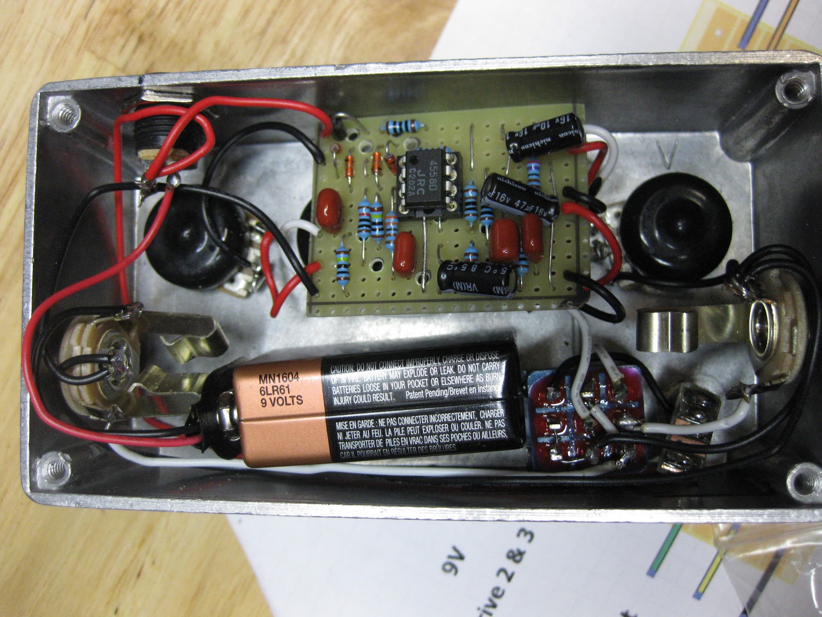
I fit's a battery pretty snugly. The wires aren't in the way of anything so I did a good job there.

The wiring inside the pedal is more of an aesthetic thing more then a functionality thing. My father said there is ALWAYS room for improvement, sometimes as a joke but it's true. I made a couple mistakes in this pedal and now I know what to do next time to make it even better. Next time I'm going to try and bend the wires in more right angles and solder the bypass switch before putting it into the pedal. The build report will be coming up soon. 

If you have any questions or comments, go ahead and write them down below