The hardest part of this build was putting everything into this enclosure. The start of fitting everything in is drilling the holes in the right place.

 For the input jacks I made it so it's the closest it can be without it touching the back plate. The DC jack is also pretty high. I tried to make it so there is a lot of space between the board and the other components.
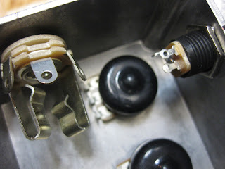 On the other side I have the output jack, LED, and the bypass switch. I wanted to push everything to the side so I can fit a batterie in the enclosure. This area is a pretty crowded area so I made sure ever measurement was precise.
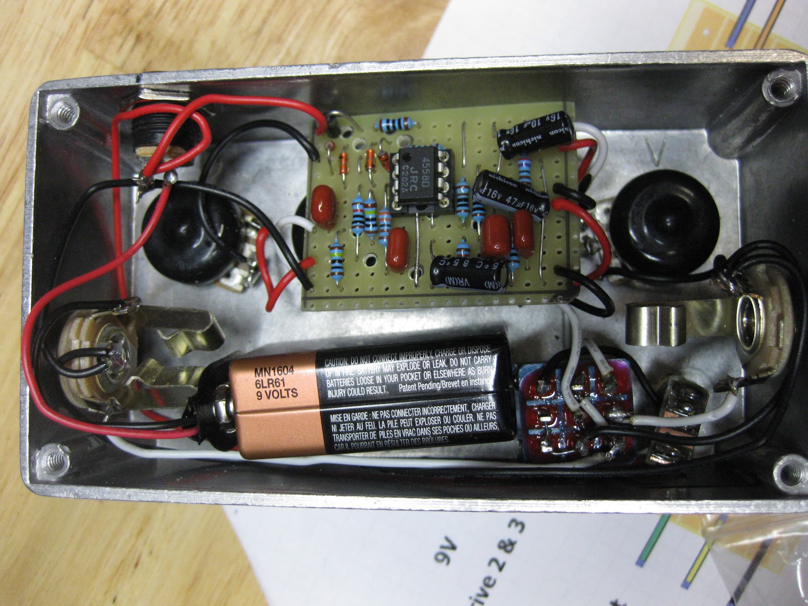
 Here is a look at the enclosure with everything in it. As you can see, the batterie fits nice and snug. The board isn't too deep into enclosure and it has a small profile.
 Recently I got some letter punches. They give the pedal a very DIY feel
 And if they don't match up or are not perfectly strait it looks even better

 I really hit that 1 hard
 The knobs look spaced out enough and the LED and bypass switch that are off to the side look pretty sweet

 This is a photo of the back plate. It's the KALAMAZOO OD, made in 2013 and has my initials
 The one thing you sure keep in mind with this step is the placement of the board. The board is the focus of the piece and everything should be positioned around it. In this pedal I made sure that everything was a far away from the board so that I will have room for my soldering iron when soldering the pots.
The second part is soldering all the wires that need to be soldered. This is pretty much the final step. When off board soldering you really want to make sure that all the wires are all routed along the sides of the enclosure. I start it off every time with the LED and grounding. I strongly suggest you have you CLR (Current Limiting Resistor) on a strip of board. This will keep it sturdy and it won't move around.
 I use the Red wire for the 9 volts coming it, and the black wire for ground. It's a little hard to see but what I have done is actually melt the shielding onto the board. This gives it a sort of strain relief when I move the wire around.
 This is the smartest way, in my opinion, to solder the CLR
 This takes up just a small part of the space.
 I note I made to myself is to solder some of the bypass switch when it's not bolted on. This will make the solder joints a lot cleaner. I didn't do that in this one


 Before putting the board in, on the layout sheet, there is usually some pot lugs that need to go to the output or the ground. Do that before you solder in the board.
 I've left the DC jack unsoldered because the 9v and G coming out of the board need to be soldered directly to the DC jack

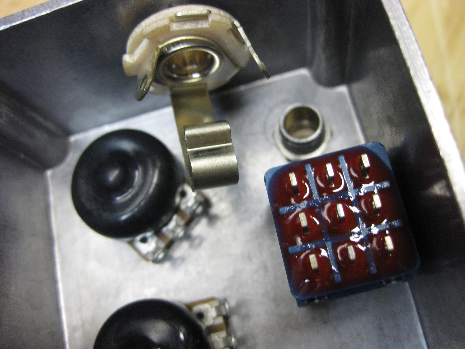
 For most drive/gain pots, lugs 2 and 3 have to be connected. Instead of using another wire, you can use pliers to bend them together. They you just need to use a bit of solder to solder them together. Make sure to leave space for a wire to pass through the lug.
 Here is another simple connection I made using a short piece of wire.
 The board needs to have a series of wires coming out of it to supply the input, 9v, ground, and pots. I like to keep it colour coated so I don't get anything confused.

 Soldering the 2 pots underneath the board was the hardest part because you have to keep the board elevated while you solder the wires under it. I used helping hand to lift up the board. It helped to cut the wire to length.
 Soldering the DC jack was a bit difficult and I probably should have routed the wires in a more neat fashion, but what done is done.


 Here is the finished product.
 I fit's a battery pretty snugly. The wires aren't in the way of anything so I did a good job there.

If you have any questions or comments, go ahead and write them down below
Here is an over view of the placement of all the offborad components


The second part is soldering all the wires that need to be soldered. This is pretty much the final step. When off board soldering you really want to make sure that all the wires are all routed along the sides of the enclosure. I start it off every time with the LED and grounding. I strongly suggest you have you CLR (Current Limiting Resistor) on a strip of board. This will keep it sturdy and it won't move around.


All the wires that need to go to the other side of the enclosure are routed on the bottom side. This will give room for the battery.


The wiring inside the pedal is more of an aesthetic thing more then a functionality thing. My father said there is ALWAYS room for improvement, sometimes as a joke but it's true. I made a couple mistakes in this pedal and now I know what to do next time to make it even better. Next time I'm going to try and bend the wires in more right angles and solder the bypass switch before putting it into the pedal. The build report will be coming up soon.
If you have any questions or comments, go ahead and write them down below


